Saturday 20 April 2013

BASIC POWER SUPPLY

                                         POWER SUPPLY


Each and every electronic circuit requires a power supply. Power supply is a heart of any electronic circuit whether  simple or complex, analogue or digital.

It is well established fact that the performance and life expectancy of an electronic circuit largely depends on the performance of its power supply. 

Alternating current it self cannot operate an electronic circuit.  It has to be converted into direct current to give life to an electronic circuit.

Three basic power supplies are given below.

1.  Half Wave Rectifier Circuit.

This is the most common and simple power supply.  Diode D1 allows positive half cycle to charge the capacitor C1. During negative half cycle diode D1 does not allow capacitor to charge and during this period capacitor C1 discharges slightly through load, however, it is recharged during the next positive half cycle.  Due to this out put D.C. voltage does not remain constant which results  in rippled D.C. voltage.  These ripples increase as the load current rises.  Therefore, such power supplies require larger filter capacitor.  Due to this factor half wave rectifier power supply is not suitable for higher and critical loads. It supports only small load (100 to 200 m.A.). e.g. relay driver circuits. 


2.  Full Wave Rectifier Circuit.
 

Full wave rectifier power supply is same as half wave circuit.  The difference is centre tapping transformer and two diodes are used instead of one.  One of the diodes allow current during positive half cycle and the other diode conducts during the negative half cycle.  This enable filter capacitor to charge during the both half cycles.  The resultant ripples in D.C. line are one half of the half wave rectifier supply.  This improves the quality of out put D.C.


2.  Bridge Rectifier Circuit.


Bridge rectifier power supply produce same results as the full wave rectifier does.  This type of supply uses four rectifier diodes connected in a bridge.  The main advantage of bridge rectifier is that it does not require centre tapping transformer thereby reducing size and cost.  During the positive half cycle diode D2, D3 conduct in series and diodes D1, D4 remain reverse biased.  While during negative half cycle diode D1, D4 conduct and D2, D3 are reverse biased.

P.S. -  Compare the out put wave form with grey shaded area in Fig1 and Fig-3, 4.  

Sunday 14 April 2013

BASIC ELECTRONICS - 2

                                                                         DIODE


As clear by name diode has two electrodes or terminals.  One is called anode and other is cathode.  It allows electricity to flow in one direction only.  It does not allow the current to flow in reverse direction.  Diode has very important role in electronic circuits. 

ANODECATHODE


The working of diode can be seen in the diagram given below.


Diode conducts only if forward biased i.e. positive voltage applied to anode and negative to cathode.  In Fig-1 diode is forward biased and allows current to flow therefore lamp glows.  In second part of Fig-1 the negative voltage is applied to cathode of diode, in this configuration diode is also forward biased therefore, lamp glows.

In Fig-2, positive voltage is applied to cathode of diode, which causes reverse biasing of diode and lamp does not glow.  similarly in second part of Fig-2, diode is reverse biased because negative voltage is applied to its anode therefore, lamp does not glow.


When diode conducts it utilises little power to conduct (push current through it).
Therefore it has a small voltage drop across it and this voltage drop is called forward voltage drop and it is 0.65 volts for normal silicon diode.

The most common use of diode is in power supply as a rectifier i.e. it converts alternating current to direct current.  All electronic circuits work on D.C. therefore, diode plays a vital role to provide power to the electronic circuits.  The figure given below shows how diode convert alternating current to direct current.

 In the above fig-3 alternating current is applied at the A.C. input.  The input A.C. waveform is shown at the left hand side of the circuit and the converted waveform is shown at the right hand side of the circuit which is available at the D.C. output.  It is clear from the diagram that the diode allows current only for the positive half cycle of the A.C. waveform and does not allow current to flow during negative half cycle.  Therefore, negative half cycle is eliminated at the output. it is rippled D.C. and can be smoothed by adding suitable electrolytic capacitor at the output terminal.  

The circuit given below shows how positive half cycle can be eliminated from the input waveform to obtain negative voltage by just reversing the direction of the diode. 

Selenium diode (rectifier)           Germanium diode            Silicon diode


Selenium diodes or metal diodes were in use mainly to convert (rectify) A.C. current in to D.C. current and they had the disadvantage of ageing process i.e. increasing resistance with use and they were suitable for low frequency only.

Germanium diodes have low forward voltage drop (0.3V) compared to silicon diode forward voltage drop (0.7V).  Older germanium diodes had larger leakage current and low reverse breakdown voltage (50V).  Germanium diodes are more heat sensitive and can be damaged while soldering.  So care should be taken when soldering.  Germanium diodes are hard to find in component shop.

The lower voltage drop for germanium diodes becomes important in signal detection for AM/FM radios.  As the signal strength in radio intermediate frequency (IF) is very low. 

Generally, germanium diodes are low current diodes, if one needs higher current diode germanium transistor can be used as a diode by shorting collector base lead together.

Silicon diodes are currently in use.  The advantage of silicon diodes are very low or negligible leakage current and high reverse break down voltage.


                                               ZENER DIODE

                                  ANODE                            CATHODE


Zener diode is like a general purpose diode which behave like any other diode if biased in the forward direction, but, if reverse biased and voltage applied across it, corsses the zener voltage (predetermined value of zener) it breaks down and start conducting to maintain the voltage (zener voltage) across it.  For the period as power supply remains above the zener voltage, the voltage dropped  across the zener diode will remain at constant level.  If the applied voltage increases further zener diode heats up and damaged if, connected directly to the power supply.  Therefore, zener diode must be reversed biased through a current limiting series resistor to sustain it over a wide range of voltage.

This quality of zener diode is utilised to regulated the D.C. voltage against supply and load variations.

Simple voltage regulator circuit.  

Zener diodes are used to stabilise or regulate D.C. voltage as shown in above circuit. Unregulated D.C. voltage between points A & B is applied to zener through a current limiting resistor R1.  The regulated D.C. voltage is available across the zener and points C & D.  Capacitor C1 plays a role of noise filter as the zener diodes, sometimes generate electrical noise which goes into D.C. supply.

The circuit shown in Fig-5 can be used to power small circuit which require low current, say 15 to 20 milliamperes.
                                                          Fig-5A

Every silicon diode has the quality to maintain voltage across it over a vide range of supply and load regulation.  This characteristic of diode can also be utilised to obtain larger voltage regulation. 

In the above Fig-5A, 10 silicon diodes are connected in series and forward biased through a series resistor.  Since, silicon diode has forward voltage drop (or forward breakdown voltage) of 0.65 V.  The net breakdown voltage of 10 diodes will be 6.5 V,  hence the output voltage will be regulated to 6.5 V.  

An Improved Voltage Regulator Circuit.


The above circuit is an improved version of a voltage regulator.  In this circuit transistor Q1 is a series pass element.  The collector of transistor is connected directly to power supply and base is connected to the cathode of zener diode, a regulated voltage source.  The regulated output is available at the emitter of transistor Q1, rest of the circuit is same as in Fig-5. 

The difference between two circuits is, the load draws current through a series pass resistor R1 in Fig-5, while in Fig-6 the load draws current from the collector emitter path of transistor. The circuit in Fig-5 is suitable for 15 to 20 milliampere current, while the circuit in Fig-6 can deliver much greater current depending upon the capacity of transistor Q1.

Zener diodes are sensitive to temperature like any other semiconductor device.  Excessive temperature will destroy zener diode, and because it conducts and drop voltage, it produce heat (W=V x I).  Therefore, care must be taken while designing the regulator circuits, so that the power dissipation in a zener diode does not exceed the safer limits.  When zener diode fails due to excessive heat , they are shorted instead of being open.  It is easier to detect such a faulty zener diode.  


                            LIGHT EMITTING DIODE (LED)

                                    ANODE                       CATHODE

Light Emitting Diode (LED) is a semiconductor which is used mainly for indicator and display purpose.  since, it is a diode therefore, it allows current in one direction only.  In the beginning LEDs were made in low intensity and colours such as red, green and yellow, but modern versions are available in many colours and high brightness.  Initially, LEDs were used in expensive  equipments such as test & measuring instruments and later in calculators, TVs &  audio equipments due to high cost.  As the technology grew and cost came down LEDs were used in domestic appliances. 

Most of LEDs come in 5MM and 3mm round package.  Now the LEDs are available in various shape and sizes.  The first high bright blue LED was made in Japan in 1994.  Typical current drawn by 3/5 MM LED is 15 to 20 mA and power dissipation of such LED is 40 to 50 Milliwatts.  However, bright white power LED dissipates up to 1000 milliwatts of power. 

The life time of a LED depends on operating temperature and current drawn.  If operated within safer current and temperature limits LED can work for 10 or more years.  High operating current and temperature can damage LED easily.

Observe the circuits given below.


Above two circuits are given, first, try (A) circuit and observe what happens.  As the LED is connected to 12 V battery it will glow for a moment and damaged immediately.  This is because current flow in LED rises abruptly to high level and heats up.  In the second circuit (B) a current limiting resistor is inserted into the circuit.  Try 2K2 resistor at first and observe the light intensity, it will glow dim.  Now check the current and try lower value resistors step by step and observe that the current drawn by LED comes within 15 to 20 milliampere.  You will see that at this current level the LED is glowing at its normal intensity.  The resistor R1 value should be 560 / 680 ohms. 

Now, take a look at the following circuits.   

In Fig-8 (A) two LEDs are connected in the circuit.  Keep the value of R1 to 680 ohms and observe the light intensity of LEDs and measure the current drawn, it may be around 10 to 12 milliamperes.  To achieve full intensity of light emitted by LED you have to reduce the value of R1 to near 400 ohm, practical value is 390 ohms. Similarly, in Fig-8 (B) you have to further reduce the value of resistor R1 (330 ohms) to achieve the current up to 20 milliampere.  

Testing of Diode :

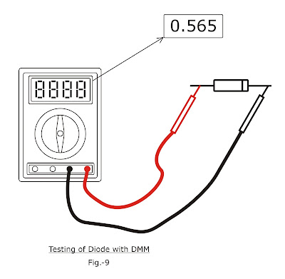
Diode can be tested by Digital Multi Meter (DMM). Set the DMM to diode test range, connect the red (+ve) probe to anode and black (-ve) probe to cathode of diode under test as shown in Fig-9 here under.  If diode is healthy the meter will show the breakdown voltage of diode, otherwise 0.00 if diode is bad.
Diode as a Temperature Sensor :

Connect a diode as shown in Fig-9 and see the reading, now place soldering iron near to diode carefully and observe the reading.  As the diode temperature rises the reading (breakdown voltage) falls down. This deviation can be utilised in temperature control circuit, however, one must have a good temperature meter to calibrate the circuit.  IN4148 or a zener diode will be more suitable for this purpose.